Ken Barry · Cork · a solo hardware and software build · first commit 3 February 2026 · in progress

A rover that is calibrated, not corrected.

Buggy is a four-wheel robot I designed, printed, wired and programmed on my own: Teensy motor firmware, a Raspberry Pi 5 Java runtime, an Android remote, a desktop console — and a computer-vision metrology lab whose only job is to measure the robot honestly instead of hiding its defects behind a gain.

206.84:1measured drive gear ratio
616floats in the measured speed map
37,201lines of Python in the measurement lab

What it is

A small robot, and the instrument that keeps it honest.

Four gearmotors with quadrature encoders, six time-of-flight rangefinders, an IMU and two cameras on a printed chassis. A Teensy 4.1 owns the motors. A Raspberry Pi 5 runs the Java server that arbitrates who is allowed to drive. Three clients — a desktop console, a touch console on the rover's own 1024 × 600 screen, and an Android app — all speak the same WebSocket.

The part I would actually put in front of a sceptic is the photograph on the right. Those four taped sheets are ChArUco boards, and a phone on a stand overhead turns them into a floor coordinate frame. Every measured constant in this project — the gear ratio, the speed map, the drift budget, the battery curve — was produced there and written into one file, rig.json, which a build-time test compares against the Java constants so the two cannot drift apart.

The rover does not depend on any of it. The lab is a teacher, not infrastructure: take the phone away and the robot still works.
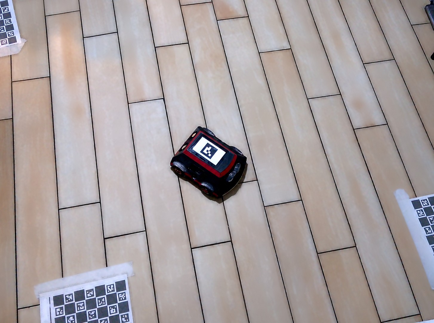
Overhead photograph of the rover on a wooden floor, with three printed ChArUco calibration sheets taped down around it; the rover is displaying a black-and-white fiducial marker on its own screen so the overhead camera can find it
The ground-truth arena, through the overhead phone camera. The rover puts an ArUco marker on its own screen so the camera can fix its pose; the taped ChArUco sheets are the tripwires that tell you whether the camera moved or the board did.

What it is not

It is not autonomous yet. It drives, it holds a lease, it refuses commands it cannot serve, it stops itself at a cliff edge and on a low pack — but there is no onboard planner following waypoints today. A closed-loop waypoint follower exists in Python, on the bench, in the lab. Getting it onto the robot needs an absolute position source better than 200 mm every ten metres or so, and that is the honest next problem.

It is not a kit with a demo sketch. It is also not a product, not a team, and not finished. The camera pan-and-tilt head on this page is drawn, dimensioned and audited — the pan column went through four adversarial review rounds, 55 defects down to 0 — but it is not printed and fitted. Where something is designed and not yet built, this page says so.

It is not network-hardened. It is built for a LAN I own; an authentication layer in front of its HTTP surface is the second item on my own written survey of what is wrong with this codebase.
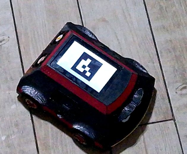
Close-up of the printed four-wheel rover on a wooden floor, black shell with a red trim band, a small screen on top showing a fiducial marker
The robot itself, photographed by the overhead rig at its own working distance — so it is soft, and it is real. Printed shell, four driven wheels, and the screen that doubles as the marker the camera tracks.
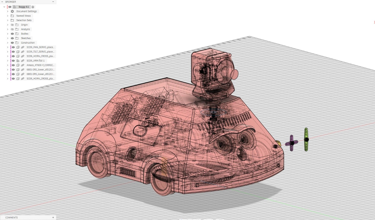
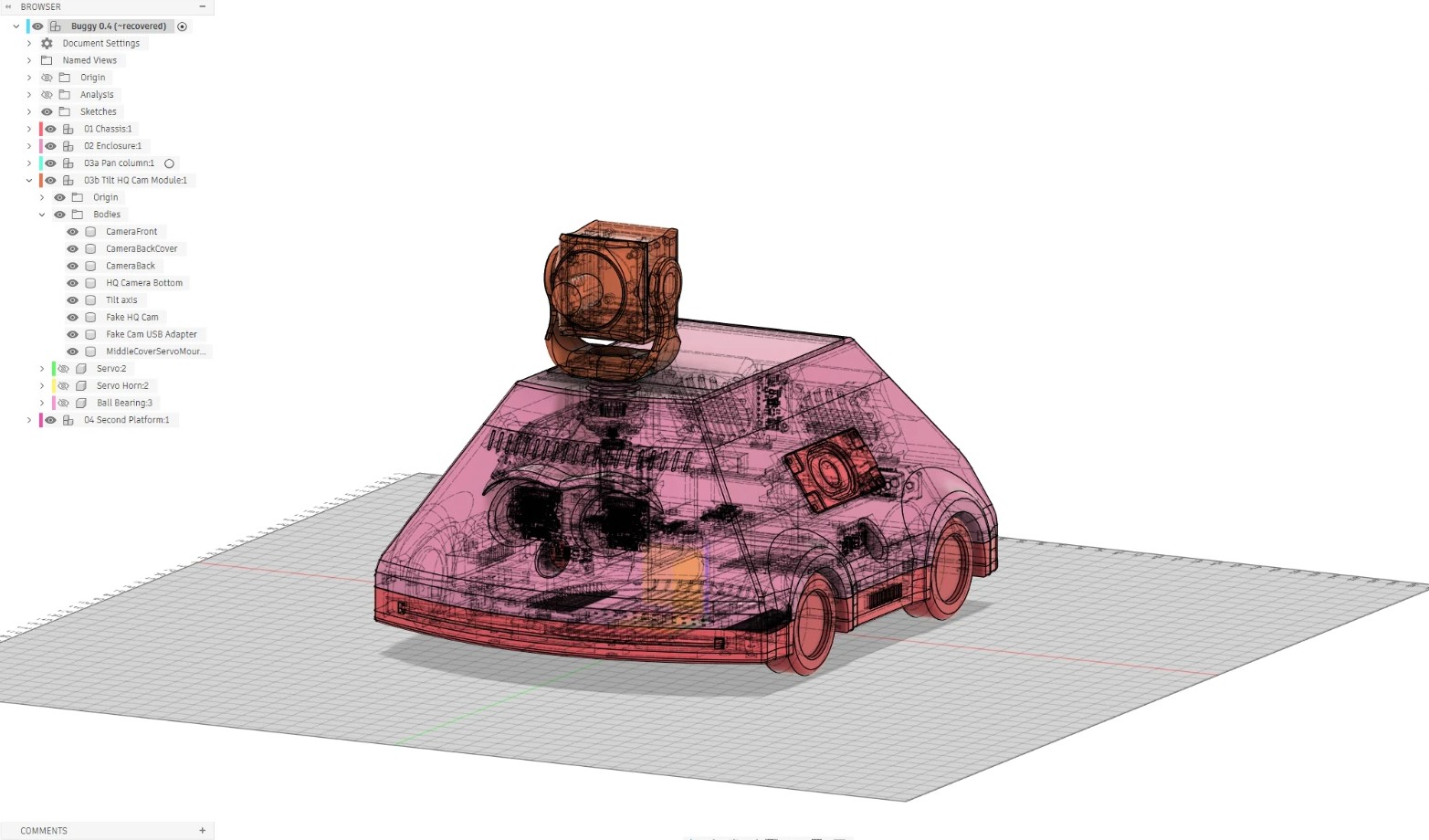
Buggy 0.4 in Fusion 360, x-ray view: two platforms, electronics, drive and the pan-tilt camera head inside the shell
Buggy 0.4 in Fusion 360, x-ray: the two platforms, the electronics, the drive and the pan-tilt camera head inside the shell.
Buggy 0.1 in Fusion 360, wireframe with the camera head
Wireframe of the same model: every part is placed, dimensioned and constrained in the assembly.
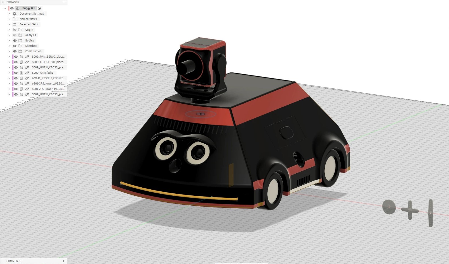
Buggy 0.1 in Fusion 360, solid view with the camera head
The enclosure as designed, with the camera head on its pan column.

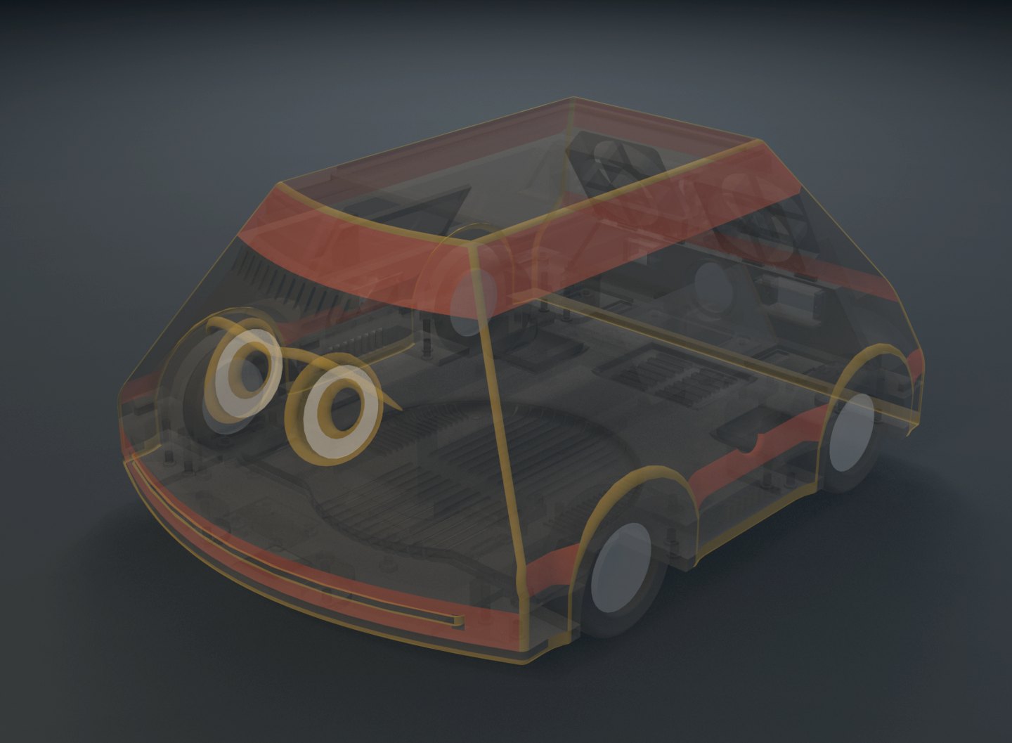
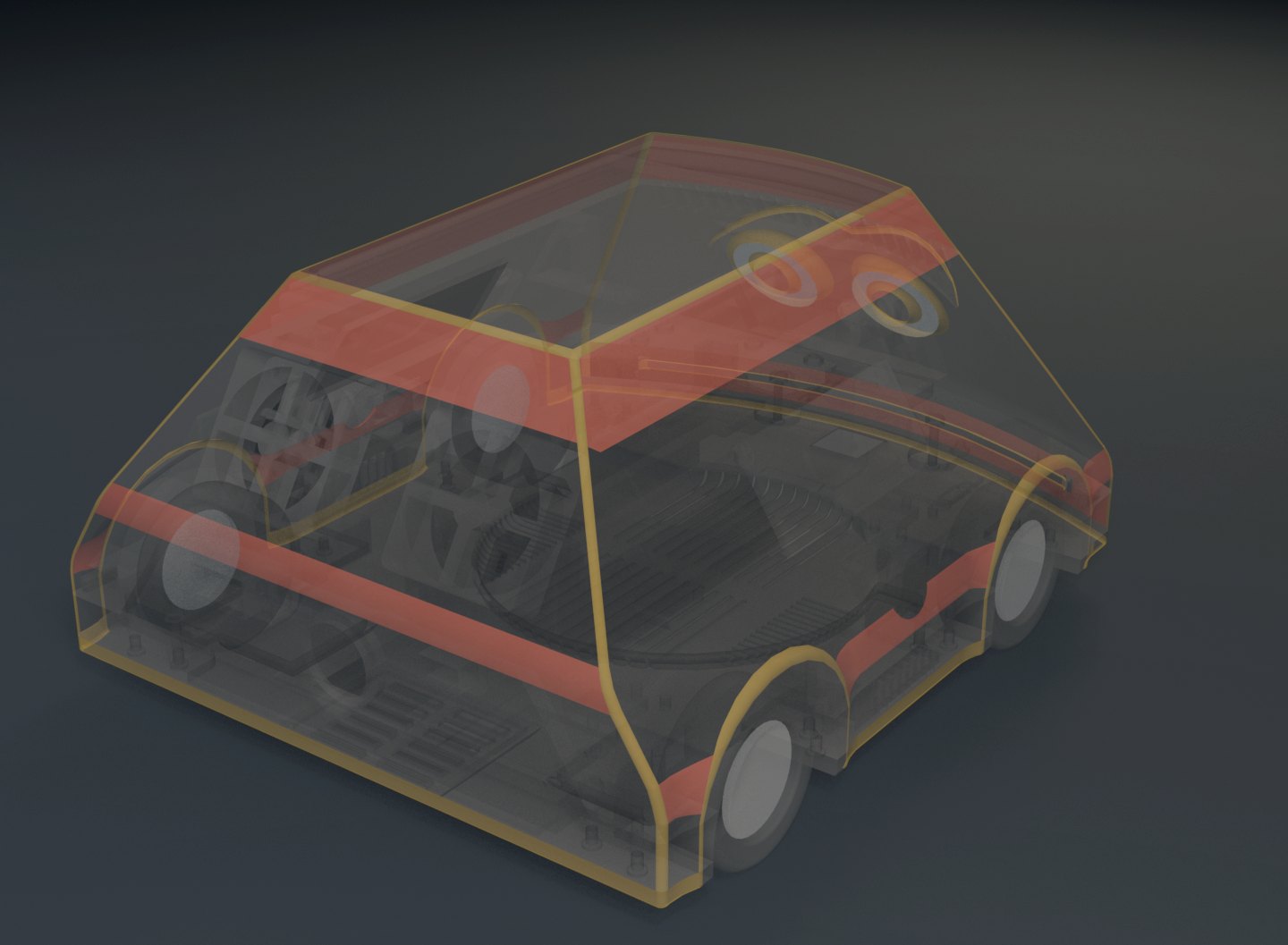
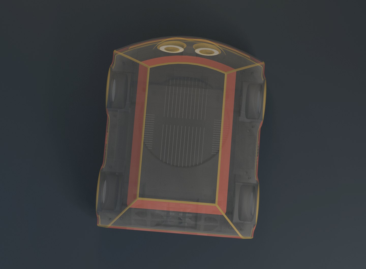
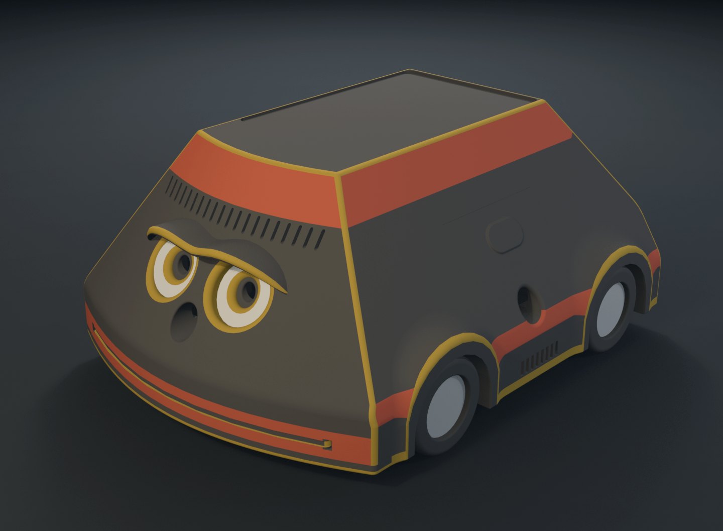
The same assembly rendered from the exported model in Blender, solid and x-rayed:
Blender render of the rover enclosure from the front
Front, solid: the two camera eyes.
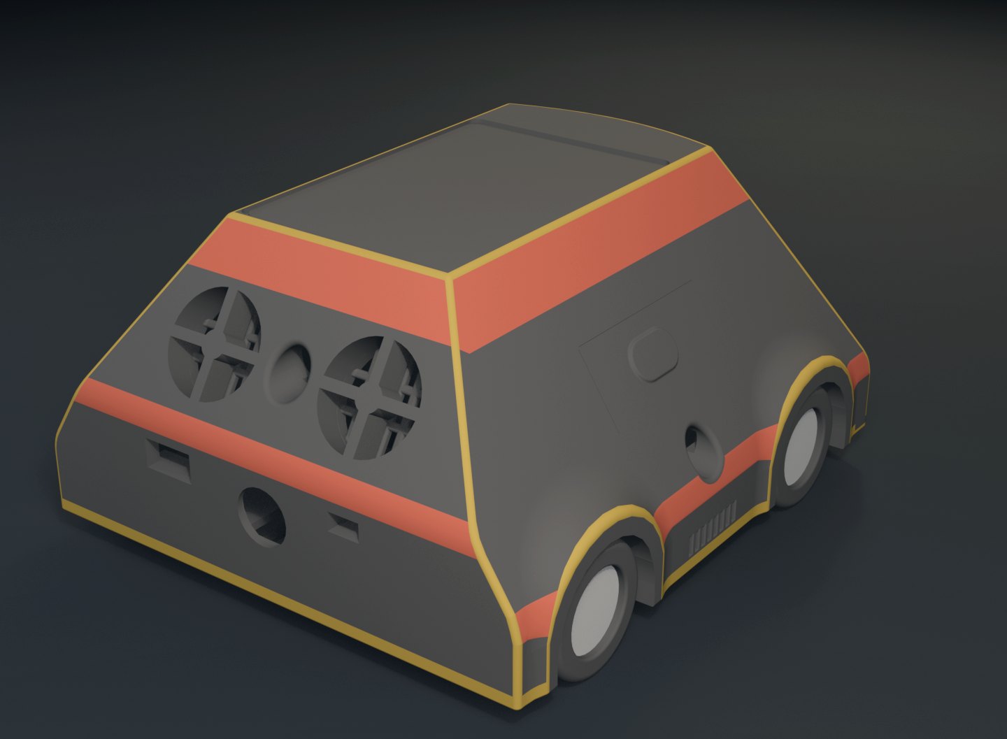
Blender render of the rover enclosure from the rear
Rear, solid: fan grilles and speaker ports.
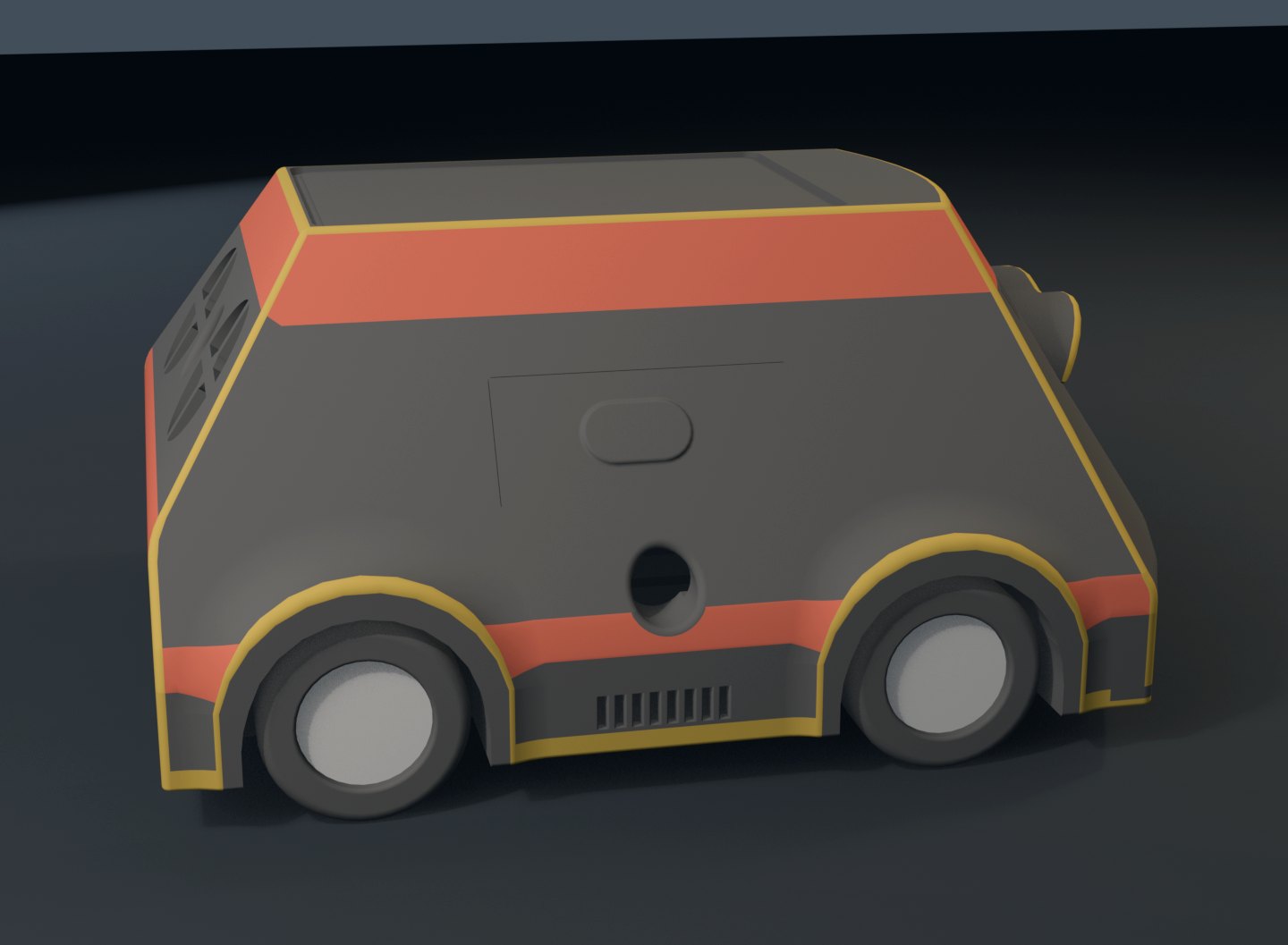
Blender render of the rover enclosure, side profile
Side profile.
X-ray render of the rover from the front
X-ray, front: platforms, fans and wheels through the shell.
X-ray render of the rover from the rear
X-ray, rear: the fan grilles over the Pi bay.
X-ray render of the rover from above
X-ray, top: baseplate, second platform, lid opening.
From above: baseplate, second platform and the lid opening.

The rule that shaped everything

The drive is calibrated, not corrected. Do not add a control loop to it.

That sentence is in the project's own instruction file, and it is the reason this robot looks the way it does. A gain makes a machine behave better and makes its defects invisible. The rule forbids that, which forces you to measure everything first.

The motor command is exactly three terms and there is no fourth:

command = table(wheel, direction, rpm)  x  voltage correction  x  aggregate load estimate

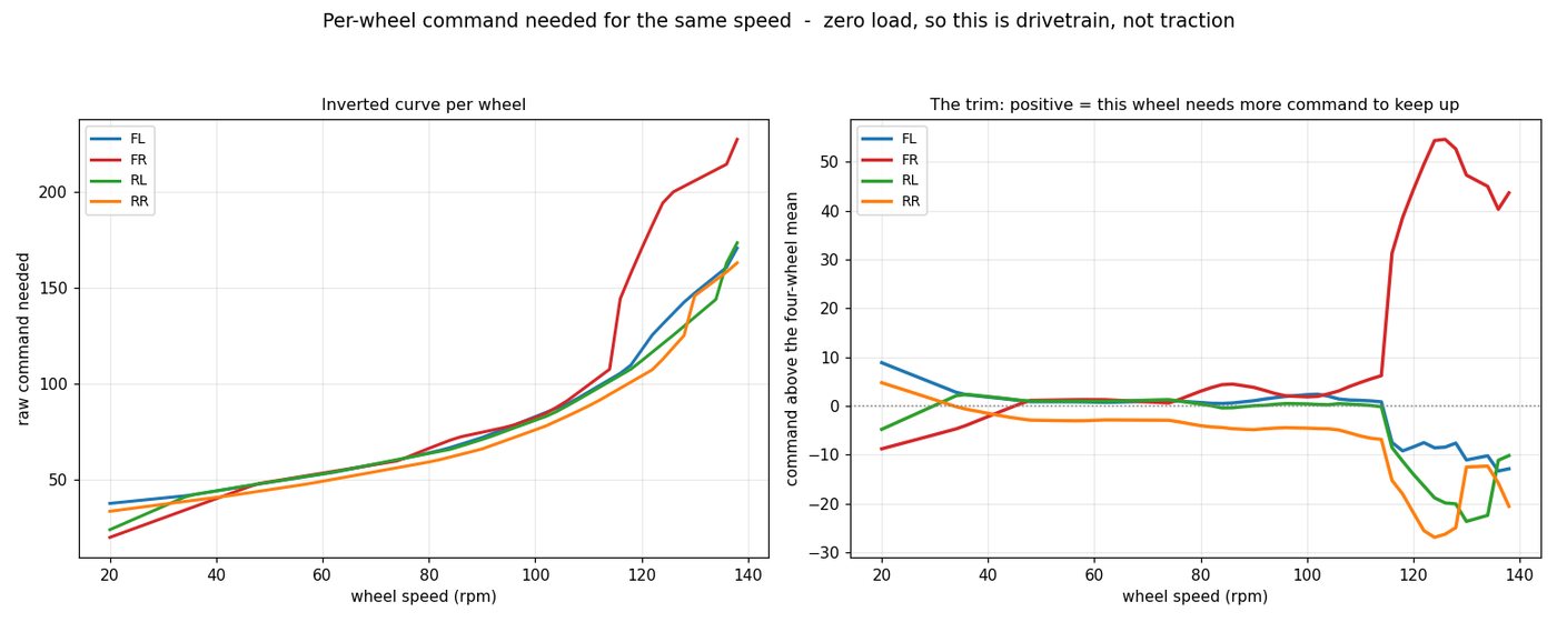
When a wheel misses its target the correction belongs in the load estimate, not in a new gain — and because the table is invertible, load is computed exactly from a single sample rather than converged toward:

load = commanded_raw / (voltage_scale * raw_map(measured_rpm))

A per-wheel PI controller sat on top of this, and it was deleted

From a standstill the error is the whole target, so proportional action alone added 77 counts on top of a feed-forward of 228. That commands 305, the driver rails at 255, and it collapses back to 236 — audible as fast-slow-fast. Narrowing the clamp to 40, then to 15, could not fix it, because a target-follower starting from a standing error always pushes, and every count it pushed was already in the table. The commit that removed it is dated 31 July 2026 and its subject is the argument:

7f9cb319e0  buggy: delete the speed PI - the map, the volts and the load ARE the controller

The four control modes are still compiled in — open_loop, closed_loop, open_loop_plus_residuals, closed_loop_plus_residuals — and the firmware publishes which one it is running. It ships open_loop. That is a decision, not an omission, and it is the one the rule demands.

Two line charts. Left: raw command needed against wheel speed in rpm, one curve per wheel, front-right needing markedly more command above 110 rpm. Right: the same data as command above the four-wheel mean, showing front-right diverging to plus 55 counts while the others fall to minus 25
The correction is not a gain — it is an inversion of the map. Left: the command each wheel needs for a given speed. Right: the trim, per wheel, against the four-wheel mean. Front-right needs about 55 counts more than its siblings at the top of the range; that number goes into the table, not into a controller.
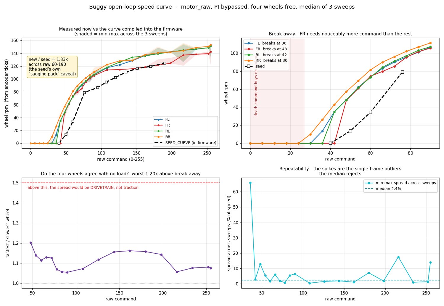
Four charts. Measured speed curve for all four wheels against the curve compiled into the firmware; break-away command per wheel; wheel-to-wheel agreement under no load, worst 1.20 times; and repeatability across three sweeps with a median spread of 2.4 percent
The re-measurement that produced the shipped map: four wheels, three sweeps, PI bypassed, median taken. The dashed line is the curve the firmware was carrying. Bottom-left asks the question that decides what kind of fault it is — above 1.5× the spread would be drivetrain, not traction. It measured 1.20×.

The real control and data path

Three clients, one authority, one wire.

Nothing below is aspirational. Every box is a file, every port is a default in the config class, and every rate was measured on the rover rather than assumed.

CLIENTS Desktop command deck autoken-buggy-ui · Java Swing 55,928 lines Rover touch console same code, on the Pi's screen 1024 × 600 Android remote autoken-buggy-app · Kotlin 6,219 lines WebSocket :8081 · HTTP :8082 · motor_pct re-sent ≤ 100 ms Raspberry Pi 5 — autoken-buggy (Java, 32,672 lines) BuggyWebSocketServer · BuggyHttpServer · BuggyTelemetryState (20 atomics, no locks) BuggyMotionArbiter — one 1 s motion lease; a commander that dies stops the rover BuggyTeensySerialService — the only thing allowed to talk to the microcontroller USB serial, newline-delimited JSON telemetry 10 Hz · encoder frames 50 Hz Teensy 4.1 — teensy_4wd_buggy.ino (4,544 lines) speed map [4 wheels][2 directions][7 pack voltages][11 rpm targets] = 616 measured floats four control modes, ships open_loop · 350 ms command deadman · envelope scaling front-ToF forward clamp and cliff latch, computed at 15 Hz Drive 4 × DRV8871 206.84:1 gearmotors quadrature encoders Ranging 6 × VL53L1X / L4CD cliff · front · both sides rear · spare Attitude and sight BNO055 IMU, fused 2 × IMX708 cameras stereo pair, 44 mm apart GROUND-TRUTH LAB — NOT ON THE ROBOT Overhead phone camera 4032 px · on a stand a marker on the rover's screen OpenCV · ChArUco 4 taped boards as tripwires worst baseline deviation 0.78 mm 37,201 lines of Python rig.json the constants file — one place every key carries why it changed Copied into constants 3 build-time tests fail on drift a test reading a file is not a dependency build time only — never commands the rover

One lease, or nobody drives

A single one-second motion lease is bound to the WebSocket connection that owns control. Any inbound traffic from the owner renews it. The gate sits inside sendMotorCommand, between the translate and the optimistic echo: zeros always pass, non-zero needs a live lease. A takeover wins in about 10 ms; a commander that dies bounds runaway at roughly 1.15 s on the wire. motor_stop is never gated.

Two independent stale-command guards

The Pi's lease is the policy; the firmware's 350 ms deadman is the physics. They fail separately and on purpose. Below them the pack itself has hard gates — resume at 11.1 V, emergency at 10.2 V, shut down at 9.9 V — so the robot switches itself off rather than deep-discharging a 3S cell.

Refusal is reported, not hidden

A skid-steer's commanded wheel ratio is the path, so serving one wheel short turns a speed request into a steering error. The firmware finds the wheel that most exceeds its own ceiling and scales all four by that single factor. motors.envelope_scale reports it: below 1.0 means the request was refused, not merely slow.

Measurement culture

A camera that is a teacher, not infrastructure.

A phone on a stand, four printed ChArUco sheets and thirty-seven thousand lines of Python turn the floor into a coordinate frame accurate to a few millimetres. Nothing in the robot's runtime is allowed to depend on it — that independence is enforced at three levels, and the duplication it creates is caught by a test.

LevelMechanismWhat it stops
SourceNo Java or shell in the runtime references the scripts or their outputs. The only reference anywhere is a test that replays recorded logs and skips when they are absentAccidental coupling
Buildtools/ is never packaged; the jar takes resources from src/main/resources onlyThe lab reaching the Pi by accident
RuntimeMeasured values are copied into Java and firmware constants, never read from rig.json at run timeA robot that needs a laptop to move
And the cost of thatDuplication drifts — so MeasuredConstantsMatchRigTest, BuggyMotionArbiterBatteryGatesMatchRigTest and a speed-map ceiling assertion compare the two at build time and fail on disagreementA silently stale constant

Some of what it measured

Drive gear ratio206.84:1 — catalogued as "210:1". The firmware carried 100.37 until this was proven with front-ToF against encoder straight-line runs, which had been overstating every odometry distance by 2.06×
Drift17–23 mm per metre of path, and essentially all of it translational — heading held to 2.8° across 2,963° of turning. Every instinct says fix the heading drift; the measurement says heading is already about twenty times better than it needs to be
IMU headingThe BNO055 under-reads turn magnitude by 4.4% (scale 0.9560, sd 0.0055, fitted on six turns). Applying it leaves 0.30° of mean error across sixteen turns. At rest the fused heading drifts zero measurably over 303 s — so do not integrate the gyro yourself, which reintroduces a bias the filter already removed
Wheel-derived headingUnsalvageable, and recorded as such: the effective track measures 356.8 mm against a geometric 193.7 mm, and swings from 244 mm counter-clockwise to 400 mm clockwise. That number is in the file to prove the approach is dead, not to correct with
Pivot quantumAbout 3.3° is the smallest useful pulse; the recommended deadband is 5°. An 8° deadband once produced a limit cycle that turned 2,963° where the path needed roughly 1,260°
Clock190 ms of rover-to-desktop residual, which at 180 mm/s is about 34 mm of position ambiguity — so an off-board fix must be taken stationary
Arena2.9063 m² of declared drivable floor, from four taped sheets and 314 detected board corners across four frames
Battery2.1–2.8 hours to motion stop, measured from 12.275 V over 1.86 h. The provisional gauge predicted 3.0 h — slightly optimistic, and the first independent check it had ever had

Each of these lives in rig.json beside a note recording what it superseded and what went wrong before. Where the lab's own README disagrees with the JSON, the JSON wins, and the README says so.

The surfaces

One console, three screens.

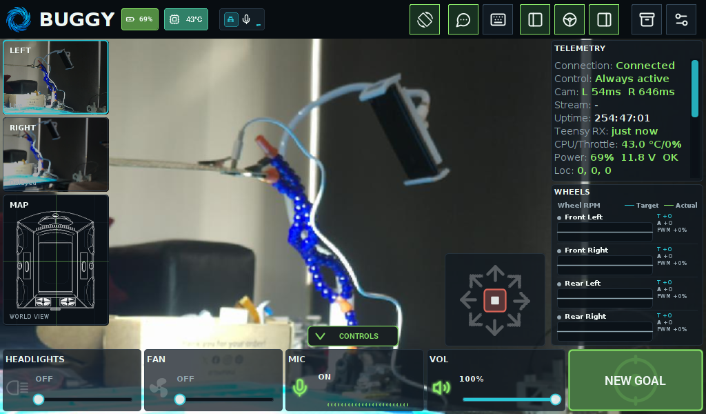
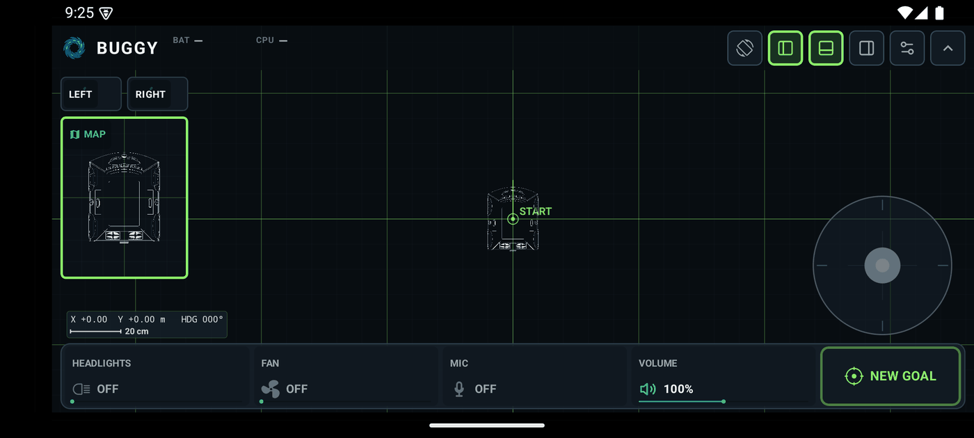
The same Java UI runs on the rover's own touchscreen and on the desktop; the Android app is a separate Kotlin client against the same protocol. The camera panes are live: what you see is the rover looking at the room.

The rover console on a 1024 by 600 screen: two masked camera panes and a plan-view map on the left, a grid world view with the rover at the origin in the centre, telemetry and four per-wheel readouts on the right, and headlights, fan, microphone, speaker and a large New Goal button along the bottom
The console on the rover\'s own 1024 × 600 screen, captured from the running rover on 15 September 2026: both cameras live, telemetry at 254 hours of uptime, wheel targets against actuals, and the goal button.
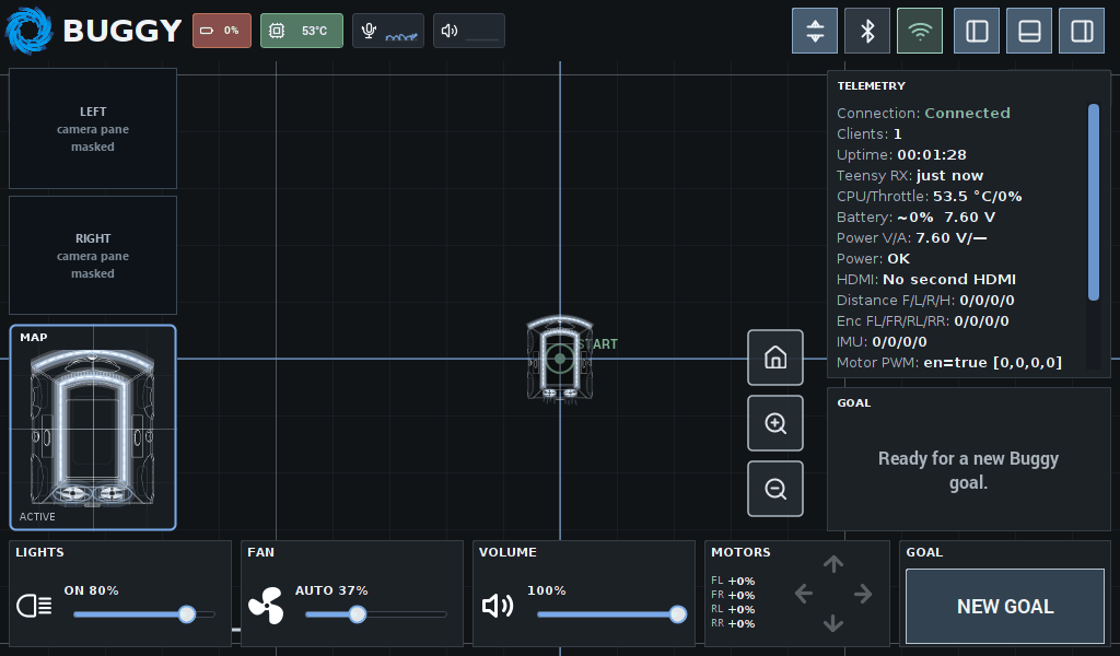
The same rover console in its telemetry layout: masked camera panes, the plan-view map, a grid world view, a telemetry column listing connection, clients, uptime, Teensy receive age, CPU and throttle, battery, power, HDMI, distance, encoders, IMU and motor PWM, and a goal panel reading ready for a new Buggy goal
The telemetry layout. Distances, encoders, IMU and motor PWM are on the face of it, because the thing that is wrong is usually one of those.
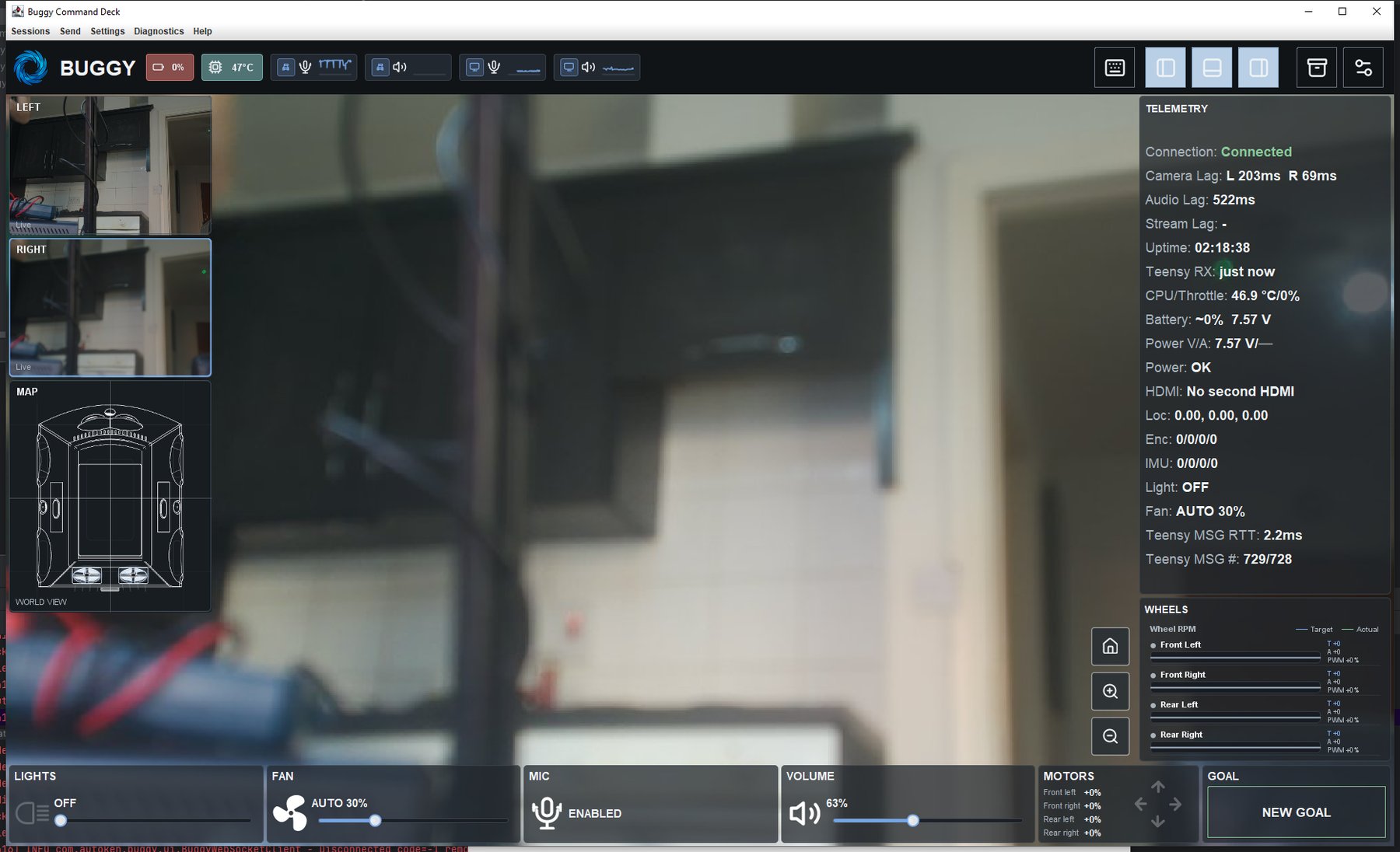
The Buggy Command Deck desktop window. The large central camera view is painted out and labelled as masked; the left column keeps the plan-view world map; the right column shows telemetry including camera lag, audio lag, uptime, Teensy round-trip time and message counts; the bottom strip has lights, fan, microphone, volume, motors and a New Goal button
The desktop command deck — the same module, given a bigger window. Teensy round-trip time and message counters are first-class, because a serial link that is quietly dropping frames looks exactly like a robot that is quietly misbehaving.
The Android rover app in landscape: camera tabs, a plan-view map panel, a grid world view with the rover at the start marker, position and heading readout with a 20 centimetre scale bar, a circular thumb joystick on the right, and headlights, fan, microphone, volume and New Goal along the bottom
The Android remote. Same WebSocket, same one-second lease — the phone has no special privilege, and if it stops renewing, the rover stops.

Hardware and CAD

Printed, wired and costed.

The chassis is my CAD. The wheel geometry, the sensor bores and the mounting datums are extracted from it into a single extrinsics file, and where CAD and a ruler disagreed, the ruler won and the file was changed.

CAD render of the rover shell from directly above: a rounded rectangular body with four wheel arches, a recessed cargo tray in the centre, vent slots and a fan pair at the rear
The current model from above, x-rayed: the same outline the console draws as its plan-view map. Wheelbase 134 mm from CAD; track 193.7 mm measured, because D-shaft adapters push each wheel about 3.3 mm outboard of where the model puts it.
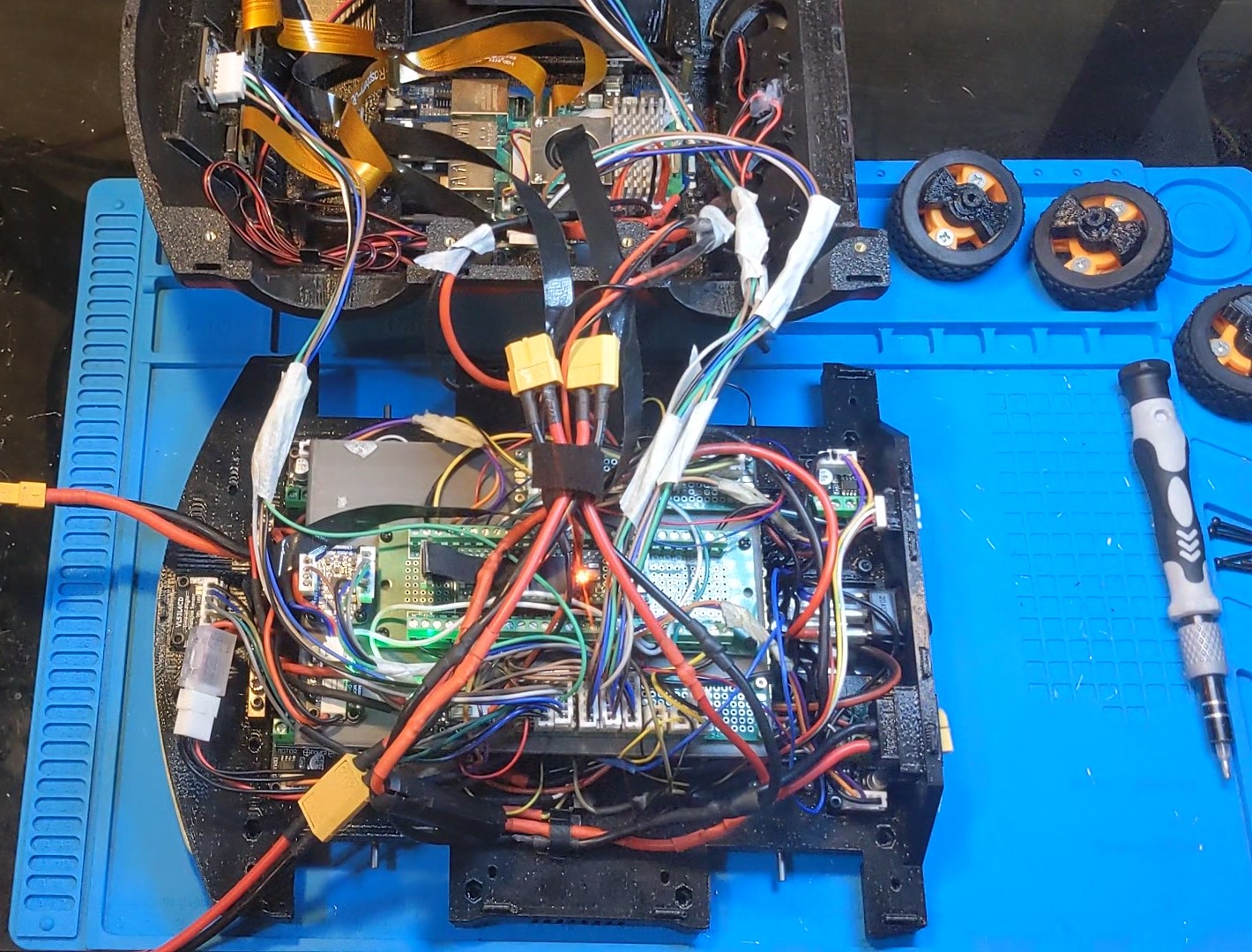
The rover opened up on a blue bench mat, seen from above: the second platform lifted back at the top with the Raspberry Pi 5, a heatsink and orange camera ribbon cables, and below it the baseplate packed with a green carrier board, driver boards, sensor breakouts and a harness of red power leads with yellow XT60 connectors, with spare wheels to the side
And the same machine with the lid off, 31 July 2026, three days after the kitchen-floor session. The second platform is lifted back at the top with the Pi 5 and its camera ribbons; the baseplate below carries the drive electronics and the battery harness, with the yellow XT60s joining the two decks.

The camera head

SC09 serial-bus servos on both axes, rated 0.7 kg·cm — not the 2.3 stall figure. They cannot take the 12.6 V pack, because the driver board passes its input straight to the bus, so a 7.2 V buck goes in series on the servo bus, not upstream. Pan axis at (x 0, y 90.7), the centre of the largest circle in the lid's flat band. Pan column verified across four adversarial rounds; the tilt module is laid out and not yet printable.

Mecanum, studied and not bought

A written options study concluded the current 47 mm wheels sit on a 3 mm D-shaft, that a 48 mm mecanum is the same class rather than an upgrade, that 60 mm costs about 28% more wheel torque and 80 mm about 70%, and that the tempting cheap candidates use 7 mm hex or 6.71 mm bores that do not fit this drivetrain. The firmware already carries forward and inverse mecanum mixing; it ships DIFFERENTIAL.

What it cost

About €1,003 as built, across 35 priced lines, from an audit of the two bill-of-materials files at £1 = €1.16 and $1 = €0.90. Roughly €421 of that — 42% — is removable on like-for-like generic parts. The single biggest line is four Pololu gearmotors at $32.45 each. The audit also found two power regulators that were bought and never fitted.

Engineering

Seven months, one pair of hands.

Java92,658 lines across 166 files in three Maven modules — 32,672 in the Pi server, 55,928 in the console UI, 4,058 in shared kinematics, pose and geometry
Firmware4,544 lines of C++ in one Teensy sketch, compiled locally on every commit that touches it
Android6,219 lines of Kotlin across 37 files
Measurement lab37,201 lines of Python across 106 files, deliberately outside the build
Commits1,987 touching the rover modules, between 3 February 2026 and 6 September 2026
Tests30 JUnit classes, including three that assert the code still agrees with the measurements
TelemetryTwelve published topics; IMU, encoders, motors, safety and world pose each at about 10 Hz, plus 50 Hz encoder frames with microsecond timestamps
ProtocolWebSocket with server-driven ping and an 8 s drop, a one-second motion lease, and a 350 ms firmware deadman under it

What is built, measurable, and switched off

This is the part most people get wrong about the project, so it is worth stating plainly: several elaborate mechanisms exist, publish their state, and are deliberately not enabled.

MechanismBuiltShipped
Closed-loop motor control4 modes, 7 tuning parametersopen_loop
Aggregate load estimatein the command formulapinned to 1.0
Learned residualsyeslab only
Cliff and front guardscomputed at 15 Hzdiagnostic
Mecanum mixingforward and inverseDIFFERENTIAL

A closed loop, a load scale or an enforced guard would each make the robot behave better and make a calibration defect invisible. The project has consistently chosen the visible defect. The cliff latch is the clearest case: it fires routinely during ordinary handling, because a rover lifted onto blocks reads infinity downward and that is indistinguishable from an edge. Enforcing it naively would immobilise the robot every time I picked it up. Separating a lift from an edge comes first.

Four things that went wrong, and what they cost

A gear ratio off by 2.06×

The firmware carried 100.37 against a real 206.84, so every odometry distance was overstated by a factor of two and every map built on it was wrong. Caught by driving straight lines and comparing the front rangefinder against the encoders. Nothing in the software could have told you.

A PI loop that sang

Proportional action from a standing start added 77 counts to a feed-forward of 228, railed the driver at 255 and collapsed to 236 — audible as fast-slow-fast. Two clamp narrowings failed before the loop was deleted rather than tuned.

A hard-coded stereo baseline

The visual-odometry estimator used 120 mm against a committed calibration that measured 44.96 mm, and never opened the calibration file it was handed. It is constructed permanently disabled, which is why nobody noticed. The build-time constants test is the pattern that would have caught it.

A strategic conclusion from a stale README

I once concluded the floor was too small to run closed-loop laps at all — 0.40 m² reachable — from a README figure, in the directory whose entire thesis is that stale figures produce confident wrong answers. The authoritative file said 2.906 m². The pointer now names rig.json, not the folder.

Timeline

  1. First rover commit: the multi-module split and the first WebSocket telemetry from the Pi.

  2. The consoles take shape — desktop command deck, the rover's own touch console, goal dialogs. The mecanum options study and the encoder closed-loop design are written and filed unpromoted.

  3. A day on the kitchen floor that changed the project: the 206.84 ratio proven, pivots shown to be mostly scrub, firmware safety guards and the single motion lease deployed and verified live the same evening.

  4. The speed PI deleted. "The map, the volts and the load ARE the controller."

  5. The measurement lab becomes the busiest part of the repository. Four ChArUco tripwires replace one board, the arena is declared, the drift budget is measured, the camera head is designed and audited, and the build is costed.

  6. Still going. 1,987 commits on the rover so far.

One more thing

A calibration test, with the sound up.

The rover on its back on the bench, 3 August 2026. It has two speakers, and neither is in use here: what you are hearing is the four drive motors. A MIDI file is parsed into a four-voice wheel score, at most four notes at a time, one per wheel, and every note becomes a speed inside the motors' 50 to 120 rpm window. Those go to the rover as ordinary speed commands over the same lease and the same measured speed map that drive it across the floor; the firmware just holds each wheel at pitch.

It is the calibration test I chose to use. A wheel that can hold a note is a wheel whose speed map is honest at that speed, and one that drifts flat is pointing at the row of the table that is wrong. Any tune would do; this one is the one I picked.

Guess the tune. Answers to the address at the bottom of the page.

Phone video, one take, sound from the motors only.

Contact

Ken Barry

Fifteen years of Java on real-time trading systems, then three years building this kind of thing alone. Available immediately, remote, based in Cork.